
Estlcam
Estlcam contains CAM and CNC motion control (firmware/interface) programs. Vector graphics (dxf and svg) and 3D (stl) files can be imported and machined using Estlcam (raster support is minimal). While doing everything in Estlcam is the simplest and most reliable route, the programs can be used individually to generate G-code for another controller (GRBL, Mach3, etc.) or to machine (simple) G-code generated by another CAM program (Vectric, Fusion 360, etc). The Estlcam control program is free, the CAM program is free to try (becomes nagware w/ increasing wait times to generate/machine G-code) and ~$60 to buy... $25 to update from v11 to v12.
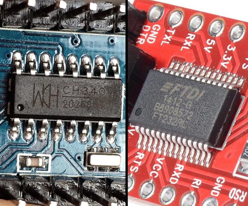
The Estcam motion control program is easy to flash onto a lot of ATmega microprocessor/GRBL compatible hardware (e.g. Uno/Nano) and Estlcam will backup anything currently installed on the hardware. If the hardware isn't recognized, USB drivers may need to be installed (drivers for FTDI or WCH serial chips are the most common). See also: Hardware
There's an extensive tutorial video for getting started with Estlcam CAM v12. The couple of versions old video playlist includes some useful topics that the v12 video doesn't cover. There's also my short videos.
This site is an attempt to provide a bit more information, things I've had issues with, what works for me, etc.. The following topics and subcategories (Carving, Hardware, Setup, v12) are pretty random and most are incomplete snippets. I've also posted a surprising amount of stuff to Estlcam International (Facebook) and the V1 Estlcam forum (mostly CAM topics). For some reason Estlcam hasn't gotten much notice/coverage in the US. If you understand German there are a lot more information and support options, e.g. most of the Estlcam YouTube videos.
Topics on this page: (newest first)
Grid Point Paths
Motion Controller Features
Tool Length Sensor
Center Origin
Autoselect and Layers
Estlcam VS Easel
Estlcam Screen Rounding
![]()
Grid Point Paths
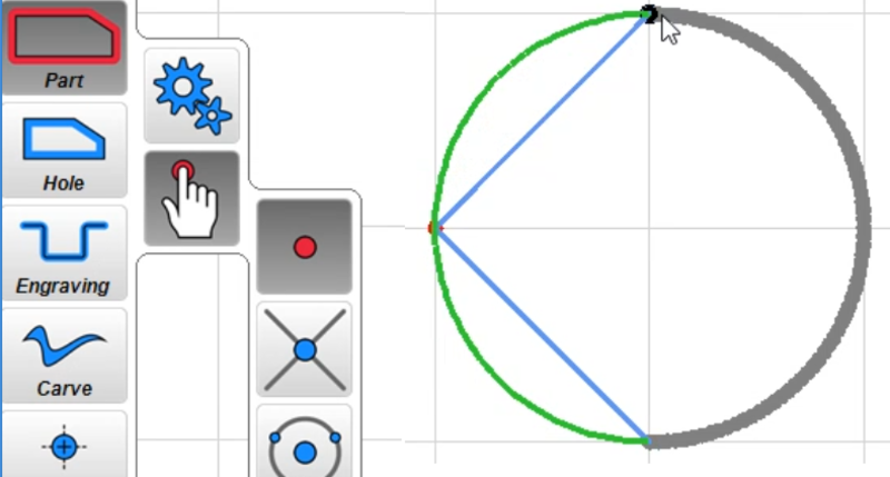 While Estlcam is not a CAD program, it can be used to create relatively simple cut paths using grid points. Left clicks create straight point to point paths and can be used to create geometric shapes. Three Ctl-Left clicks will create an arc, five a circle. To create a circle of a desired size set the grid spacing (View : Grid) to the desired radius (...or Select and Resize)... It seems that v12 cannot do arcs/circles.
The video was created in response to a question about creating multiple circles so it includes a Select : Tile example. I also threw in an Edit : Group (anytime one click selection/editing of all items in the group) and Automatic Functions : tabs (length/height adjustable in the group Properties window).
Estlcam Grid Point Paths - YouTube
[ comment | link | top ]
Motion Controller Features
- Tool change support
- M06 pause w/ message box (automatically added by Estlcam CAM)
- manual or 1-click Z probe/0 reset
- v12: tool length table (ATC or collars)
- Spindle on/off and PWM speed control
- keyboard, mouse or (Estlcam CAM auto inserted) G-code
- v12: input, hotkey(s) and macro switchcable
- Program (machining) start/pause
- mouse or momentary switch control (plus Esc or G-code pause)
- v12: configurable hot key(s)
- anything can be done during a pause (or F11 released "stop")
- program can be resumed (or started) at any point in the G-code
- restarted interface will offer a remembered resume point
- Stored origins and paused coordinates
- origins remembered until changed, no shutdown loss
- automatic (offer to) resume from paused coordinates
- Program end rewind
- click play icon to run the G-code again
- Eight direction continuous (or step by step) jog
- keyboard, mouse, wire(d/less) numpad, joystick, XBox gamepad, MPG pendant
- v12 has new mouse wheel options and changes to supported hardware
- five or variable speed jog
- command box incremental (default) or absolute jogging, (a)axis distance
- keyboard, mouse, wire(d/less) numpad, joystick, XBox gamepad, MPG pendant
- On the fly feed and speed control
- keyboard, mouse, remote or potentiometer
- Inputs:
- Conductive block or tape probing/touch-off
- manual nine direction w/ auto reverse
- spinning bit tape probing (accurate straight flute touch-off)
- circle or rectangle (w/ angle comp) center finding
- v12: edge intersection and circle center to circle angle comp
- auto 3 axis corner (w/ angle comp)
- auto cycle Z zero tool change
- 3D Surface scan
- Homing/limit input switches
- any (set to 'limit switch') input pin(s) can be used
- (all) switches can be wired in series (NC, w/ Invert) or parallel (NO)
- none required
- v12: macros (input or hotkey) and more
- Conductive block or tape probing/touch-off
- Outputs:
- mouse or G-code (M08/9 on, M10/11 off) control
- v12: auto G-code insertion, hotkey and custom icon support
- Command entry box
- xy - goto X,Y origin
- goto [foo] - G-code search w/ path highlighting (v12: go [foo])
- abs/rel - switch between machine (abs) and workspace (rel) coordinates
- 'axis distance' incremental move, A'axis distance' absolute move
- v12: all command line options can be used in v12 macros
- etc.
- Drag knife support - adds pivot offset to paths
- v12: on the fly surfacing tool
- v12: some hideable tool icons
- Compatibility:
- G-code:
- G00-G03, I/J, F/S, M00-M11 sans M02/4/7
- all coordinates are relative to project origin (absolute, no G90/91 switching)
- unsupported G-code is ignored
- Hardware:
- most ATmega328/2560 based hardware, e.g. Arduino and many GRBL boards
- G-code:
[ comment | link | top ]
Tool Length Sensor
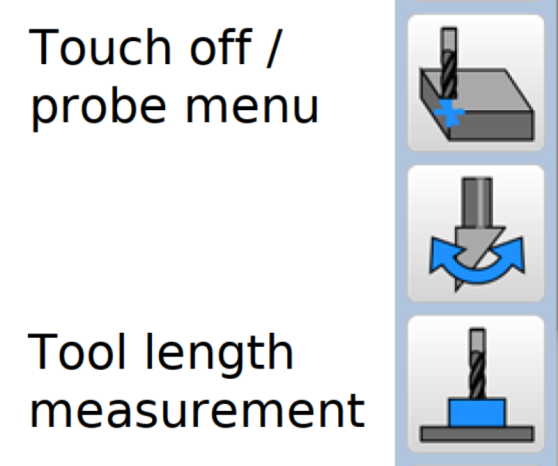 As with any Estlcam probe function, the probe plate can be a simple piece of aluminum (tape) wired to a "probe" input. Using the one click automatic tool length measurement function speeds up and simplifies tool changes, no probe menu navigation or manual touch off required. While a 3-axis probe plate makes a handy sensor, a spoilboard mounted sensor is needed if the surface of the material will be machined away.
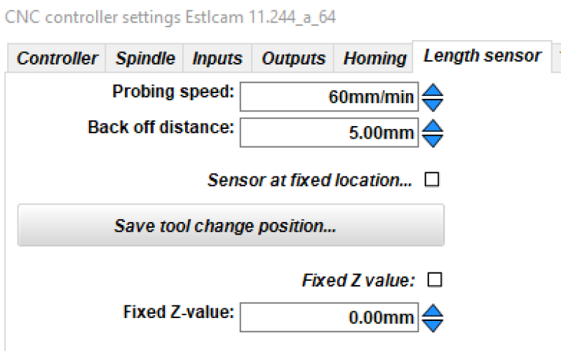
To setup the sensor go to Setup : CNC controller : Length sensor. I use a speed of 60mm/min for all automatic probing functions. The settings fixed location option requires homing be enabled, but a fixed location at (what I use), or relative to, the project origin/0,0 point is also possible (Texts : Tool change).
Warning: Unlike other probe options, the Z-axis will start moving when you click the icon. When you move the tool over the sensor and click the icon, the tool will automatically travel down, touch and retract. After the first touching off of the tool length sensor, the material top also needs to be touched off/zeroed. After that the sensor will automatically adjust the Z-axis zero point after tool change sensor probes. Note: 1) After a sensor touch off, Esc does nothing and the message will only go away when you do something else. 2) The default 6mm/min speed is typo - super slow, pretty much undetectable (v11.244)... 3) The offset is not stored, restarting Estlcam requires a material touch off to recreate it.
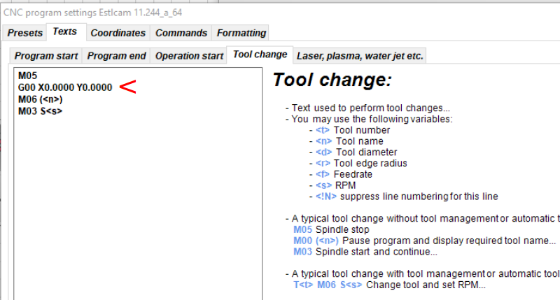
A 3-axis probe plate works great for one-off projects where the corner won't get machined away. With the tool a bit in from the corner (wherever you normally start a 3-point probe) start by clicking the length sensor icon. Do the 3-point auto probe after and you're good to go. After tool changes go to that 'in from the corner' position, slide the probe plate in position and click the length sensor icon. To have the machine automatically go to that 'in from the corner' position for tool changes, add G00 coordinates (e.g. G00 X15.0000 Y15.0000) to Setup: CNC program : Texts : Tool change.
[ comment | link | top ]
Center Origin
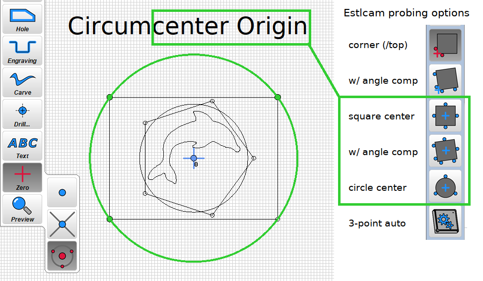 A center origin is used when you want to center a project/drawing on the material being cut. It's easy when the drawing has a center point mark or the drawing includes a perimeter circle, rectangle or regular polygon. Those shapes all have a circumcenter (three point/triangle circumcircle center) and using the three point center option will center the origin.
When using the Estlcam controller the center finding probe options will precisely center the bit on the material and automatically zero X/Y. Less precise alternatives include manually measuring and marking the center, making intersecting arcs with a compass set to half the diameter, etc. followed by manually centering the tool on the marks and zeroing X/Y.
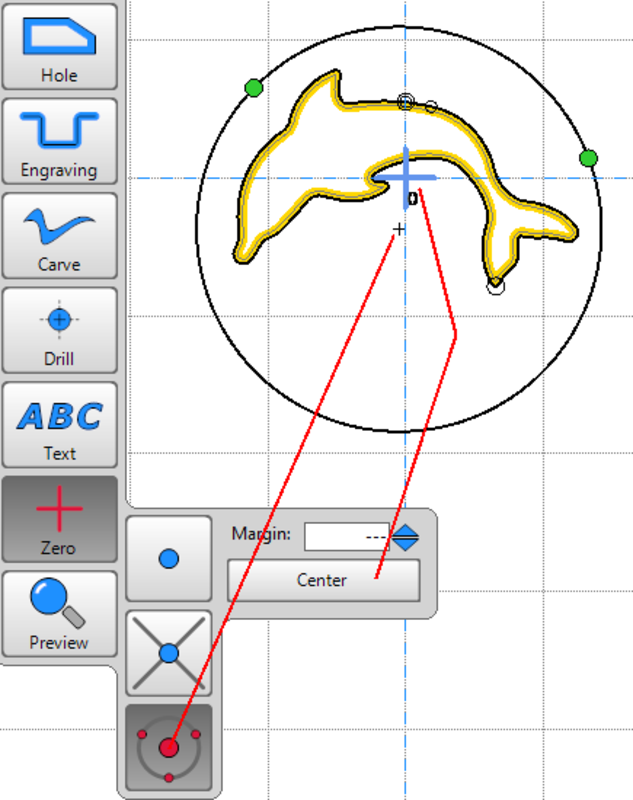 ...New in v12 is a one click origin at the Center the set paths. When a perimeter path is set (e.g. the circle), it does everything the three point tool does and more. For drawings without a perimeter, e.g. just the dolphin path, it may not provide the desired center (the 3-point tool will). A third option is to center the drawing/origin on a grid point (34sec YouTube).
[ comment | link | top ]
Autoselect and Layers
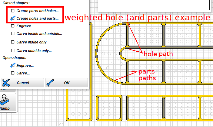 Even on simple projects, having CAM programs auto-select cutting paths (Automatic Functions : Create objects automatically) can be hit and miss (...Estlcam v12 autoselection is much improved). If the project involves more than one type of cut, e.g. inside and outside of the line, auto-select will be weighted to one or the other and paths will probably need to be edited. Easel auto-selects by default and provides three unweighted options (in/out/on) when importing a drawing. Estlcam auto-select is optional, includes more cut types (e.g. drilling) and the multiple (de)selectable options are weighted (e.g. image) / constrained (e.g. holes under/over a specified size get drilled/routed). Unlike Easel, Estlcam can read DXF layers which makes (auto-)selection so much easier.
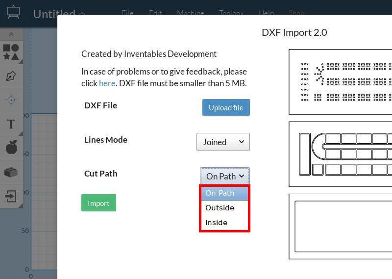
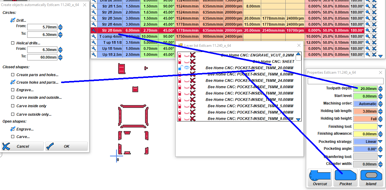 This example image is a layered DXF generated by the BeeHome project and imported into Estlcam. The layer names provide all the information needed to auto-select (e.g. weighted inside/hole) and set the parameters for cutting the paths (bit size, cut depth and pocket). I spent a whole lot of time on just one part of that DXF trying to edit all the paths in Easel before deciding it was just too tedious for a one off project.
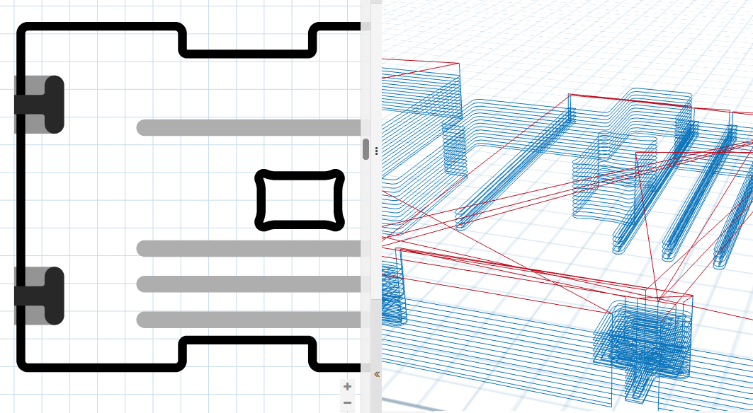
While Estlcam can lock/unlock DXF layers to allow (auto-)selecting paths by layer, running auto-select multiple times (e.g. on multiple layers for multiple bits/DOC's) requires locking the already selected/configured paths and the layer so that they don't get modified or re-selected on subsequent runs.
Since it took me a while to get it:
The View : Layer list : layer lock only prevents the creation of (new) paths on that layer.
The Edit : Lock only prevents the modification of already created and selected paths.
Locked objects are grayed out, only layers can be completely hidden (or deleted/restored).
Note: There is no need to 'unlock all' and there seems to be a bug (v11.244) where hole/part paths can revert to on line when unlocking all (...has only happened to me once).
Grouping (Edit : group) allows one click path properties editing and locking of all items in the group, i.e. path layerlike functionality. My goal is to create drawing layers that will work well with autoselect and allow me to group paths with like properties. The grouped paths make anytime property edits (tool, DOC, machining order, etc.) so much easier.
Depending on the project, I use Autosketch or Inkscape for creating my layered DXF files... Because I find Inkscape easier for text and Autosketch easier for geometry, I've found a use for Estlcam File : Insert (...replaced w/ a new Add function in v12) which adds the inserted file as a new layer. Only DXF and .e10 (Estlcam project files) can register automatically with the current project... The v12 Add function requires registration markers and using Move to be able to register the added file with the current project, see video for details.
When Opening (or Updating) a drawing file Estcam creates a bounding box bottom-left origin. When using the v11 Insert option Estlcam uses the origin embedded in the drawing file (could be anywhere). DXF files will only register with the current project if they have a bounding box bottom-left origin. The top-left of inserted Inkscape SVG images will register with the Estlcam default origin (seemingly regardless of the SVG page origin). I was registering inserted SVG's by fiddling with X/Y coordinates (Move DXF) until I discovered that inserting saved as v14 DXF (with an appropriate origin) removes that hassle. It was also cool to discover that Estcam project files can be combined via Insert, e.g. I now have an insertable keyhole cutting project file.
...It seems that Estlcam has a problem with (too many?) identical objects (stacked) on multiple DXF layers, e.g. with only one layer active some of the duplicated objects may be missing. Since any DXF object can be used to create any number of paths there is no need for duplicate objects. Planning reusable layers takes a bit more work, but the end result can be simpler and easier to use (less layers)... Fixed in v12.
[ comment | link | top ]
Estlcam VS Easel
One of the key functional differences between Estlcam and Easel is that Easel can only cut inside/outside of a closed line/path (e.g. a circle). Any shape with ends that don't meet (e.g. a line) can only be "Cut on shape path". I'm guessing that the closed line restriction/awareness is why Easel will never cut into an adjacent line (on the same closed path). Any irregular pocket cutting (e.g. text) with a straight bit is affected. If the space between two lines is smaller than the bit, Easel won't cut it.
 While Estlcam will cut into the adjacent line if the space between two lines (e.g. text) is smaller than the bit, it can cut to the right/bottom or left/top of open paths, e.g. lines. While this is a very useful feature, e.g. being able to cut a shape on the end/edge of a board, it has some bass-ackward constraints.
 The Engraving default is bidirectional cutting. While bidirectional cutting is fast and efficient (great for roughing) any machine/bit flex will create noticeable ridges on the cut face because each pass will flex the machine in the opposite direction, i.e. not ideal for hobby level machines... On the other hand, I wonder if light bidirectional engraving with a V-bit (or ball end) might make for a cleaner cut (less fuzz).
The solution (when one side of the cut is waste) is to add a finishing tool pass to right or left of the line cuts. It's not a very efficient solution because both the roughing and finish pass cuts are unidirectional. While less than ideal, the loss of bidirectional roughing would be acceptable if the configured cut direction settings were honored, they are not.
When a finishing tool is selected, right of the line cuts are always climb cut and left of the line cuts are always conventional cut (both cut bottom to top, top and bottom of the line paths are cut right to left). The cut direction workaround is to manually set the point to point path (1st point = cut start)... This actually works well for radiused corners which can be conventional cut with the grain (t/l and b/r corners) and climb cut against the grain (t/r and b/l corners).
... Selecting right of the line and setting a point to point path in a conventional cut direction works for all conventional cut paths (left of the line for climb), e.g. left to right = below the line conventional and right to left = above the line conventional. Note: This is the opposite of what happens when using auto select (above image). Setting a default bidirectional path for roughing (w/ a finishing allowance, w/o a finishing tool) and a separate/second full depth (so its not bidirectional) point to point path for finishing might be the most efficient solution... but it requires a duplicated tool with a finishing/full depth DOC for the primary/default setting (VS the secondary/finishing).
...Estlcam Engrave with finish pass example (v11 CAM) - YouTube
Example of using Estlcam Engraving to create a bidirectional roughing path and a climb cut finish pass using the point to point tool (manual shape detection, left click to select any point, right to select/set the green line as a path). It's a bit of a hack that is only possible w/ v11. It requires a duplicate tool definition that allows a full depth cut by default. The large finishing allowance was just to make the finishing pass more noticeable in the preview.
... v12: A unidirectional finishing pass is no longer possible because _all_ cuts are bidirectional. While its possible to get a conventional (or climb) cut with a separate full depth point to point path it is totally unreliable. Each run of my test cut alternated between starting the cut at the top and bottom of the line which in turn alternated the finishing pass start point, i.e. conventional to climb to conventional. I wonder if allowing the addition of a start point could be added to the engraving function.
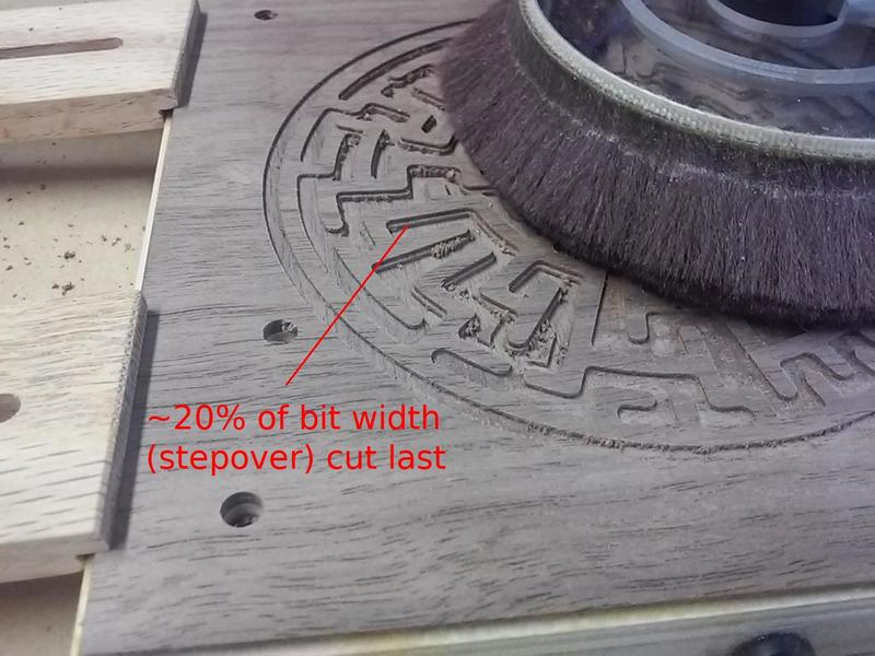 Another area where Estlcam and Easel differ is when cutting pockets. The example is a complex maze and both programs were set to cut parallel/offset (Estlcam changed/Easel default). Both generated paths that jump around a lot and it isn't obvious which moves around more. Both appear to use an ~40% stepover, but Estlcam leaves an ~20% path around the perimeter. While this does result in an additional path in some places, that 20% path is cut last - no finish pass required... Side note: Estlcam set to parallel provides the best results on narrow pockets, but the algorithm is too conservative/safe, i.e. too many unnecessary and time consuming passes... because parallel stepover is limited to 45% (regardless of bit settings).
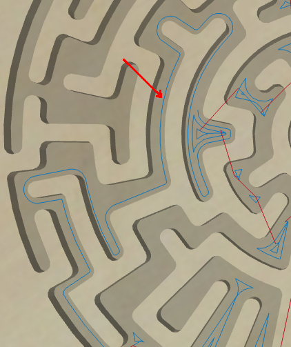 The Easel generated path includes some full width cuts along the perimeter (more likely to leave wall marks and top tearout). While both can leave islands (which can break and tear grain) and it would be nice to see everything cut from center out, Estlcam saving the perimeter for a 20% wide final pass is a big plus.
...While there are a lot more Easel VS Estlcam topics, I no longer teach Easel classes and it's been over a year since I logged in/have done anything Easel related.
[ comment | link | top ]
Estlcam Screen Rounding
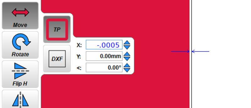
While entering something like 8.016mm for X-axis distance per revolution will be rounded to 8.02 on screen, the stored/used number will be 8.0159997940063477. I have no idea where that number comes from*, but it is only off by .0000002mm. For a frame of reference, the rounded .004 difference divided by 20,000 equals the .0000002 stored/used difference.
...All G-code numbers have four decimal places (default). While setting a .0001mm tool property (e.g. DOC) is rather pointless (too small to be realistic), it will show up in the G-code as entered even though the tool property entry is is rounded to 0.00mm.
... It looks like all inputs will accept/use numbers with four decimal places, e.g. the Move function (.25mm path moved -.0005mm at max zoom)... A forum post led me to the discovery that the tool diameter field (and likely others) can have at least 10 decimal places, but G-code rounding to 4 decimal makes using more decimal places pointless.
...*Thanks to that forum thread I also learned about floating point numbers. Using a converter I was able to confirm that Estlcam is storing 32-bit floating point numbers in the configuration file. I wouldn't be surprised if all user entries are converted to 32-bit floating point numbers for internal use and rounded to 2-3 decimal places for external use.
[ comment | link | top ]