
Home : Workshop : Electronics :
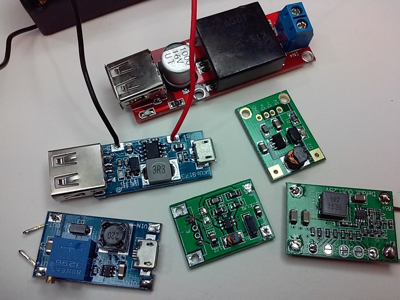
 Working with low voltage direct current can involve batteries and/or multiple voltages. Changing voltages is accomplished with step-up and/or step-down voltage converters. Some converters are also capable of charging batteries. My current uses for these boards involve charging 18650 batteries and converting their 3.7 volts to 5, 9 and 12v. Following is some information on some of the various boards I have used.
 I've tried a few, but I just ran across a pretty good article that tests 6 different modules
[ link | top ]
 These small (17x13x5mm, ~5/8x1/2") red boards have a minimum input of 2v and a claimed maximum output of 2a (only possible with small step-up, e.g. 4 > 5v). The 9v one is supposed to be able output .51-.63a while drawing 1.59-1.65a (82.3-85.7% efficiency) from a 3.5-4v source (e.g. 18650).
The 9v version of this board appears to be ~5% less efficient than the the 9v step-up/charger (w/ ~50ma load). but makes up for it in size. Replacing the stock inductor with a 5020 and placing it back to back with a 03962A charger makes for a very compact step-up/protected charger (smaller than the unprotected combo board).
[ link | top ]
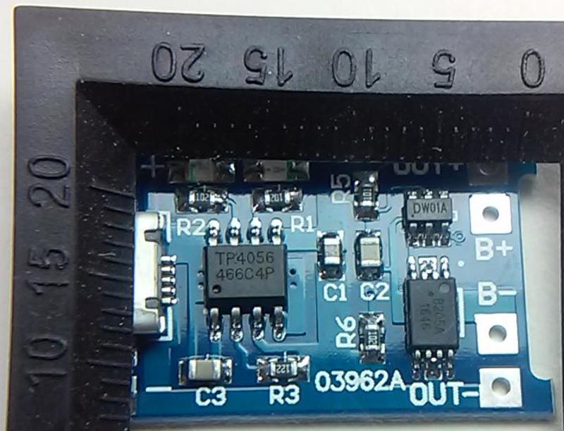
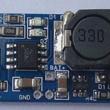 This board charges lithium batteries at .5a and outputs 9v up to .5a. It works as advertised and may be the most efficient 9v step-up I've tried. It's unfortunate that the charger uses a 4056ES* charge controller and has no protection circuit. The board measures 34 x 17 x 5.5mm and is a bit bulky due to the rather large inductor. The location of the battery pads in the middle of the board is less than ideal, as is the lack of input pads.
Removing the micro USB and hardwiring the input can be a bit tricky. Twice I've ripped off the 5v trace and had to add a new trace routed to an isolated USB socket housing pad... I've since had good results using two irons, one for the housing and one with a tip that can contact all 4 traces. Two irons also make replacing SMD resistors easier.
*See: 5v Lithium Charger for more info on the 4056ES charge controller.
[ link | top ]
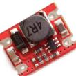
 There are a number of similar boards, this one advertises 2-6v input (3a max) and 5-16v output (<= 8w). The board is bigger (33 x 16 x 6.5mm), has larger components, and could be capable of producing an advertised output that is significantly higher than the other boards on this page, e.g. .89a VS .5a @ 9v. I've replaced the rather tall CD75 6R8 inductor (5mm, 2a) with a shorter 0630 (3mm, 4.5a), but have yet to test the board with any significant load.
At this writing, all US sellers seem to be selling the 12v output version. The output voltage appears to be set by R2 which is 287k for 12v, 210k for 9v and 100k for 5v. Those values were taken from pictures of boards advertising the associated output. Based on that, I ordered some 180k resistors and will see if I get the expected 8v output (TPA3110 min)... I got a hair over (8.1?), but it won't run the TPA. I'm not sure if the mod (are any other components different on the lower voltage boards?) or the voltage (I haven't tried running the TPA at 8v) are the problem.
[ link | top ]
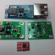
 A USB/5v charger for lithium batteries. This charger has a protection circuit that will prevent over (dis)charging. The same charger is available with micro (some w/ mini pads) or mini USB inputs (...also USB-C). There are similar looking chargers without the protection circuit. The difference is that the protected charger has three IC's (black, multiple legs) instead of one on the unprotected board... Unfortunately, there are numerous manufacturers of the 4056 charge controller used on these boards.
I don't know which chip the board I tested had, but the charger is rated at 1a and I saw .91a w/ an under powered wall wart. The charge cut-off voltage was ~4.18V (better than the over 4.2v of some other chargers, 4.2 = 100% and 3.92v is best for longevity*) and the discharge protection cut-off was ~2.6v (better over 2.5 than under, but I'd prefer 3.2v). Over current protection is listed as 3a (untested). Note: The first time you hookup a battery you also need to hookup the charger (5v/USB) or the circuit may not work (some sort of flip-flop in the protection circuit).
The default charge rate is too high for some batteries. The R3 resistor can be changed to achieve a desired charge rate (rate in amps/resistor in kΩ): .13a/10k, .25a/5k, .30a/4k, .40a/3k, .50a/2.4k, .58a/2k, .69a/1.66k, .78a/1.5k, .90a/1.33k, 1.0a/1.2k.
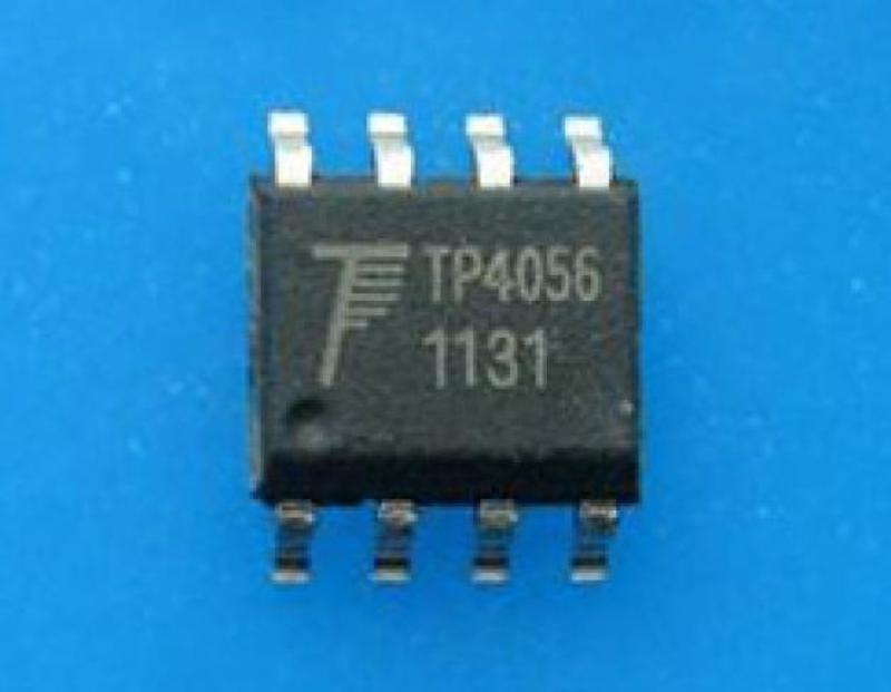
The various 4056 controller IC's used on these boards do not behave the same. It is claimed that the NanJing Top Power TP4056 are the original chips and that all others are clones/fakes. While the NanJing chips are available on Aliexpress, I have not seen them on any current boards. The following are my random observations regarding particular 4056 IC's (all w/ .5a rate and same battery):
TC4056A: 4.22 cut-off, made by Shenzhen Fuman Electronics
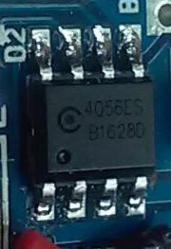
4056ES w/ C dot logo: Charge rate decreases to .38a @ 4.20v and .20 - 0a @ 4.22 (no load). When there is a load and the charger is plugged in, the load is always powered by the charger. The minimum loaded charge rate equals the load current. While the battery may be charged, the blue led will never light when there is a load.
Three strikes:
1) No charged indicator when there's a load
2) "Higher [than 4.20] charge voltages boost capacity but lowers cycle life and compromises safety."*
3) A battery "dwelling in a full state-of-charge for an extended time can be more stressful than cycling"*
Note: Tested board was a charger/9v step-up .
TP4056 (466C4P), no logo/name: Charge rate decreases to .28a @ 4.14v and .09 - 0a @ 4.17. When the battery reaches full charge (0a/blue led), any load will be powered by the battery until the battery voltage drops to 4.05v and the charger kicks in (red led).
Pluses:
1) Charged indicator works under load
2) Cut-off voltage is slightly less than 4.2v
3) "A partial discharge reduces stress and prolongs battery life, so does a partial charge."*
... While the printing looks different, TP4056 (466C1Z) chip functionality appears the same.
TP4056 w/ TPower name/logo: I pulled the plug after it got to 4.23v, i.e. it is not the same chip as the above no name/logo TP4056 IC. Note: tested board was an unprotected variant of the 03962A board.
Note: charge rate amps were taken from the 5v side.
*How to Prolong Lithium-based Batteries
[ link | top ]
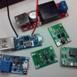
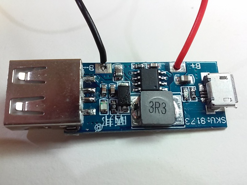
 This board can charge a Lithium battery OR step-up the battery voltage to 5v. It will only output 5v when the charging cable is removed. When the charging cable is attached (charging or not), the board output equals charge voltage (bypassing battery and step-up). This prevents simultaneous (dis)charge of the battery and is good for applications where discharge rates would exceed the boards .6a charge rate (e.g. power banks). This board is not suitable if you need to run something at 5v (< .6a load) while the battery is being charged. The lack of in/out hardwiring pads is a minus, as is the relatively high 4.22-4.23v charging cut-off.
There are at least three different manufacturers of, or markings on, what appear to be identical boards. Mine has SKU: 8173 printed on the top of the board, another has 150303000?, and one has no markings.
The smallest possible overall dimensions are 45 x 15 x 5 (w/ A socket tabs bent flat). Without the USB A, 33 x 15 x 4 (thanks to the ceramic inductor). It is rated at 0.6a charge and 1.0a discharge.
The board uses a FM6316FE IC which handles the charging and the step-up to 5v.
[ link | top ]
DC Converters and Chargers
 Working with low voltage direct current can involve batteries and/or multiple voltages. Changing voltages is accomplished with step-up and/or step-down voltage converters. Some converters are also capable of charging batteries. My current uses for these boards involve charging 18650 batteries and converting their 3.7 volts to 5, 9 and 12v. Following is some information on some of the various boards I have used.
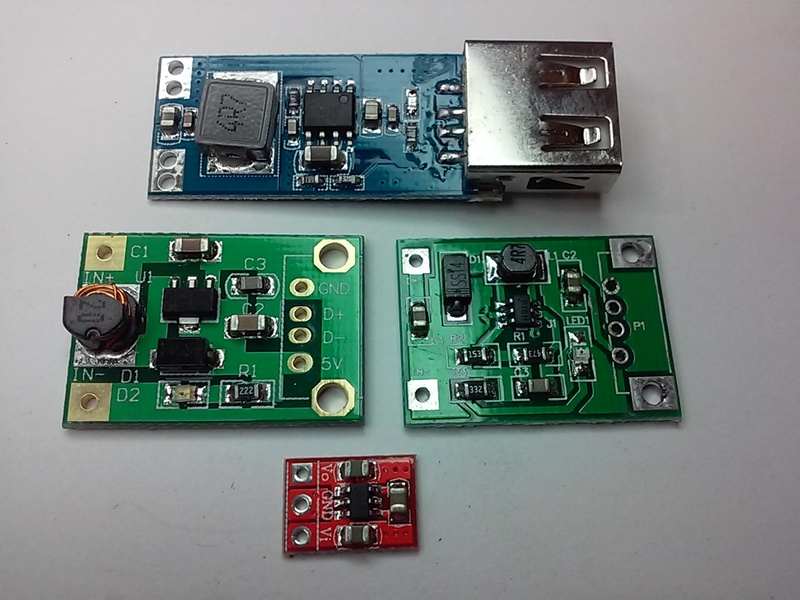
5v Step-down
 I've tried a few, but I just ran across a pretty good article that tests 6 different modules
[ link | top ]
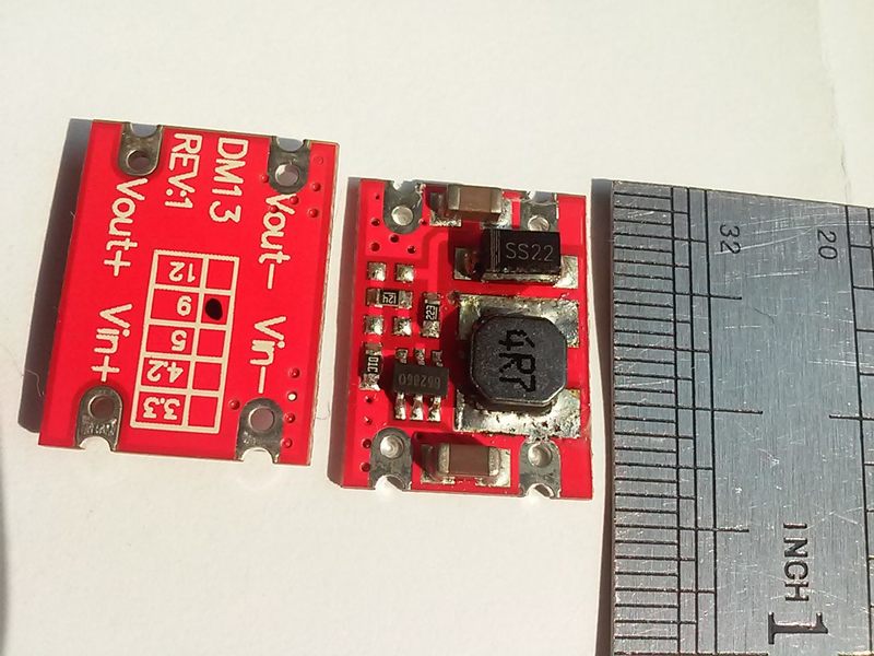
3.3-12v Step-up - DM13
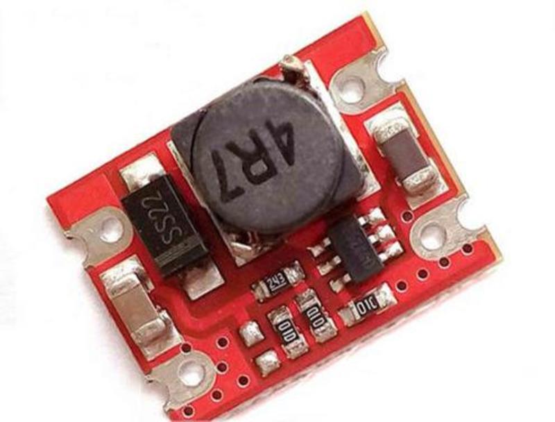 These small (17x13x5mm, ~5/8x1/2") red boards have a minimum input of 2v and a claimed maximum output of 2a (only possible with small step-up, e.g. 4 > 5v). The 9v one is supposed to be able output .51-.63a while drawing 1.59-1.65a (82.3-85.7% efficiency) from a 3.5-4v source (e.g. 18650).
The 9v version of this board appears to be ~5% less efficient than the the 9v step-up/charger (w/ ~50ma load). but makes up for it in size. Replacing the stock inductor with a 5020 and placing it back to back with a 03962A charger makes for a very compact step-up/protected charger (smaller than the unprotected combo board).
[ link | top ]
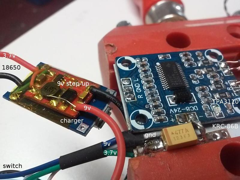
5v Charge and 9v Step-up - 2016.5
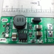
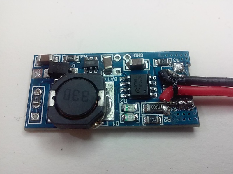
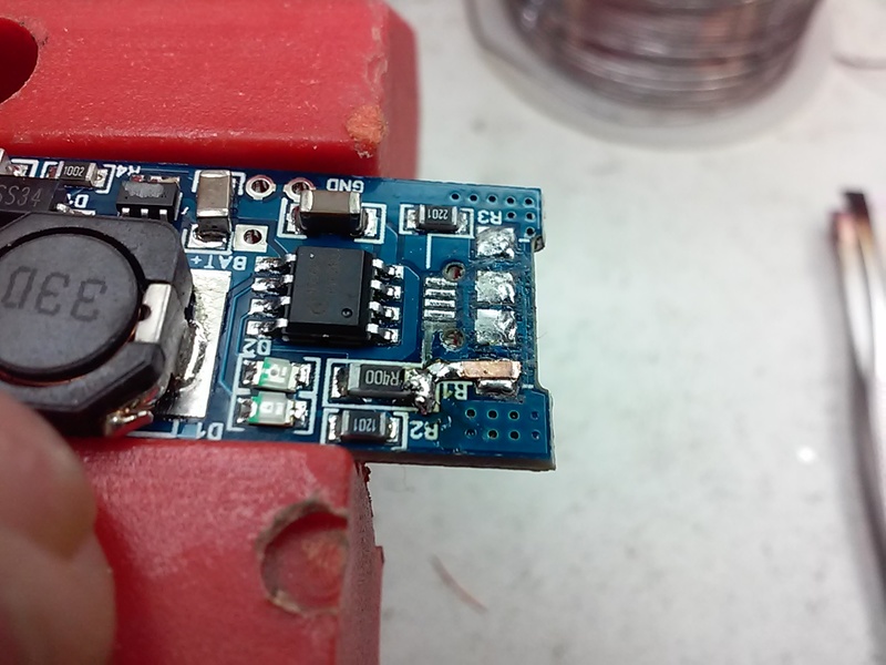
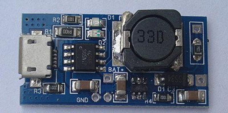 This board charges lithium batteries at .5a and outputs 9v up to .5a. It works as advertised and may be the most efficient 9v step-up I've tried. It's unfortunate that the charger uses a 4056ES* charge controller and has no protection circuit. The board measures 34 x 17 x 5.5mm and is a bit bulky due to the rather large inductor. The location of the battery pads in the middle of the board is less than ideal, as is the lack of input pads.
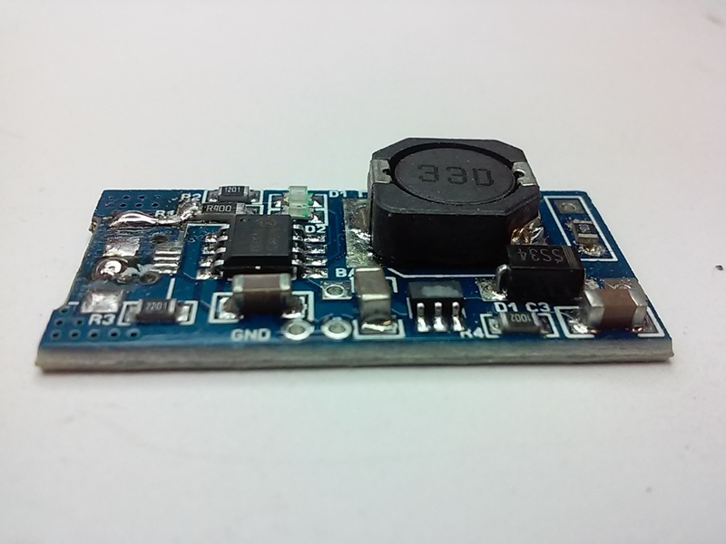
Removing the micro USB and hardwiring the input can be a bit tricky. Twice I've ripped off the 5v trace and had to add a new trace routed to an isolated USB socket housing pad... I've since had good results using two irons, one for the housing and one with a tip that can contact all 4 traces. Two irons also make replacing SMD resistors easier.
*See: 5v Lithium Charger for more info on the 4056ES charge controller.
[ link | top ]
5-16v Step-up - SD XMDZ
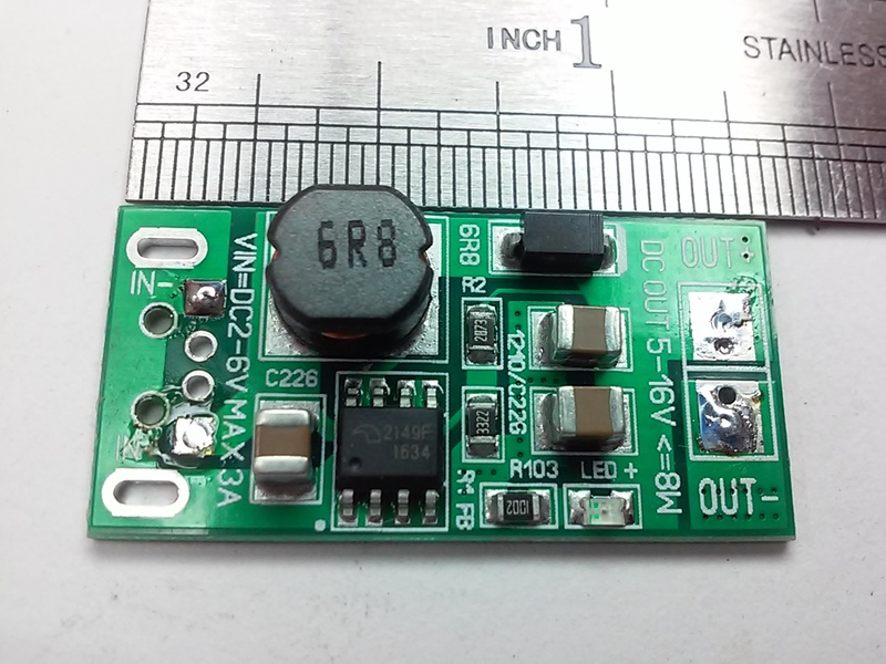 There are a number of similar boards, this one advertises 2-6v input (3a max) and 5-16v output (<= 8w). The board is bigger (33 x 16 x 6.5mm), has larger components, and could be capable of producing an advertised output that is significantly higher than the other boards on this page, e.g. .89a VS .5a @ 9v. I've replaced the rather tall CD75 6R8 inductor (5mm, 2a) with a shorter 0630 (3mm, 4.5a), but have yet to test the board with any significant load.
At this writing, all US sellers seem to be selling the 12v output version. The output voltage appears to be set by R2 which is 287k for 12v, 210k for 9v and 100k for 5v. Those values were taken from pictures of boards advertising the associated output. Based on that, I ordered some 180k resistors and will see if I get the expected 8v output (TPA3110 min)... I got a hair over (8.1?), but it won't run the TPA. I'm not sure if the mod (are any other components different on the lower voltage boards?) or the voltage (I haven't tried running the TPA at 8v) are the problem.
[ link | top ]
5v Lithium Charger - 03962A
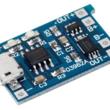
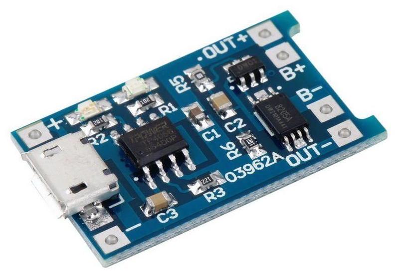 A USB/5v charger for lithium batteries. This charger has a protection circuit that will prevent over (dis)charging. The same charger is available with micro (some w/ mini pads) or mini USB inputs (...also USB-C). There are similar looking chargers without the protection circuit. The difference is that the protected charger has three IC's (black, multiple legs) instead of one on the unprotected board... Unfortunately, there are numerous manufacturers of the 4056 charge controller used on these boards.
I don't know which chip the board I tested had, but the charger is rated at 1a and I saw .91a w/ an under powered wall wart. The charge cut-off voltage was ~4.18V (better than the over 4.2v of some other chargers, 4.2 = 100% and 3.92v is best for longevity*) and the discharge protection cut-off was ~2.6v (better over 2.5 than under, but I'd prefer 3.2v). Over current protection is listed as 3a (untested). Note: The first time you hookup a battery you also need to hookup the charger (5v/USB) or the circuit may not work (some sort of flip-flop in the protection circuit).
The default charge rate is too high for some batteries. The R3 resistor can be changed to achieve a desired charge rate (rate in amps/resistor in kΩ): .13a/10k, .25a/5k, .30a/4k, .40a/3k, .50a/2.4k, .58a/2k, .69a/1.66k, .78a/1.5k, .90a/1.33k, 1.0a/1.2k.
The various 4056 controller IC's used on these boards do not behave the same. It is claimed that the NanJing Top Power TP4056 are the original chips and that all others are clones/fakes. While the NanJing chips are available on Aliexpress, I have not seen them on any current boards. The following are my random observations regarding particular 4056 IC's (all w/ .5a rate and same battery):
TC4056A: 4.22 cut-off, made by Shenzhen Fuman Electronics
4056ES w/ C dot logo: Charge rate decreases to .38a @ 4.20v and .20 - 0a @ 4.22 (no load). When there is a load and the charger is plugged in, the load is always powered by the charger. The minimum loaded charge rate equals the load current. While the battery may be charged, the blue led will never light when there is a load.
Three strikes:
1) No charged indicator when there's a load
2) "Higher [than 4.20] charge voltages boost capacity but lowers cycle life and compromises safety."*
3) A battery "dwelling in a full state-of-charge for an extended time can be more stressful than cycling"*
Note: Tested board was a charger/9v step-up .
TP4056 (466C4P), no logo/name: Charge rate decreases to .28a @ 4.14v and .09 - 0a @ 4.17. When the battery reaches full charge (0a/blue led), any load will be powered by the battery until the battery voltage drops to 4.05v and the charger kicks in (red led).
Pluses:
1) Charged indicator works under load
2) Cut-off voltage is slightly less than 4.2v
3) "A partial discharge reduces stress and prolongs battery life, so does a partial charge."*
... While the printing looks different, TP4056 (466C1Z) chip functionality appears the same.
TP4056 w/ TPower name/logo: I pulled the plug after it got to 4.23v, i.e. it is not the same chip as the above no name/logo TP4056 IC. Note: tested board was an unprotected variant of the 03962A board.
Note: charge rate amps were taken from the 5v side.
*How to Prolong Lithium-based Batteries
[ link | top ]
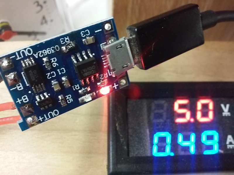
5v Charge OR Boost - 8173
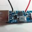
 This board can charge a Lithium battery OR step-up the battery voltage to 5v. It will only output 5v when the charging cable is removed. When the charging cable is attached (charging or not), the board output equals charge voltage (bypassing battery and step-up). This prevents simultaneous (dis)charge of the battery and is good for applications where discharge rates would exceed the boards .6a charge rate (e.g. power banks). This board is not suitable if you need to run something at 5v (< .6a load) while the battery is being charged. The lack of in/out hardwiring pads is a minus, as is the relatively high 4.22-4.23v charging cut-off.
There are at least three different manufacturers of, or markings on, what appear to be identical boards. Mine has SKU: 8173 printed on the top of the board, another has 150303000?, and one has no markings.
The smallest possible overall dimensions are 45 x 15 x 5 (w/ A socket tabs bent flat). Without the USB A, 33 x 15 x 4 (thanks to the ceramic inductor). It is rated at 0.6a charge and 1.0a discharge.
The board uses a FM6316FE IC which handles the charging and the step-up to 5v.
[ link | top ]