
Home : Workshop : Metalwork :
 A carriage stop is a must for any operation where relocating the cutter position using the compound slide is impractical. This stop uses an incremental thread (e.g. 1mm or 1/32" pitch) and a zero mark (e.g. the setscrew) so that the stop position can be accurately set, measured and reset at any time. For finer adjustment, a faceted head (e.g. a decagon for .01mm/~.0004") could be used. The stop has a range of ~2" with the minimum setting a bit less than I've ever needed, the maximum a lot more (...jinxed, I had to switch to a longer screw for this setup)
The body, knurled head and lock-nut were made from 1/2" aluminum rod. The knurled head was tapped, mounted to a threaded rod with a setscrew and then faced. The aluminum body was tapped for the threaded rod on one end and has a clearance hole on the other. Because tapping the clearance hole for a mounting stud would have required a larger diameter stud than I wanted, I used a short bolt for mounting. The aluminum is threaded for the bolt and the bolt was center drilled/tapped to mount it to the stud (a long setscrew). The mounting stud location is as low and to the front as I could get it - using my smallest cordless drill for drilling the pilot hole. Ideally the head of the stop would hit the carriage, but I had to be content with it hitting the top bar of my carriage lock.
...Added a ring that goes on the drive lever to remind me to retract the stop.
...Made a limit switch attachment that hooks up to the chuck guard interlock wiring. 18sec YouTube video.
[ comment | link | top ]
 I use a Grizzly T10056 scissors knurling tool with the small side lip butted to the back of the tool post. It's held in place with two of the three screws and located with almost no clearance between it, the tool post side and the chuck. I have a small centering reference arrow drawn on the carriage (near the bottom right of the image) that aligns the centers of the knurler wheels with the center of the chuck.
To setup, I start with the knurler centered, tighten the knurler until both wheels are touching the material to be knurled, back the cross slide off a few turns and then turn the knurler knob a bit more than a quarter turn. To knurl, I move the cross slide forward until both wheels are contacting the work hard enough to leave a decent impression. I then manually turn the chuck at least one full turn to insure I have a good pattern. That first turn is the most important and being a bit aggressive on the pressure helps to prevent a running/overlapping pattern. I then run the mill at slow speed and move the cross slide forward until the wheels are centered on the chuck (my arrow). I've been leaving it there for 30 seconds, about when I stop seeing flakes appearing on the knurling wheels. With larger diameters I have had to back the slide off a bit, (to be able to) turn the knob a bit tighter, and move the slide back forward to get nice pointy knurl peaks (on aluminum).
With the stock wheels I had to take a bit off of 1/2" stock to get a good knurl. I flattened those wheels trying to knurl something too hard. The replacement wheels (different brand) work fine on 1/2", but 5/8" needs to be turned down a bit. While the ideal material diameters for a given set of wheels should be easy to know, I didn't have much luck with the math (e.g. PJ's knurling pages). If I cannot get a good pattern on the first turn, I try a deeper first turn before resorting to turning the diameter down a bit. A deeper first turn is possible when only a portion of the wheels contacts the stock, e.g half on/off the left end of the material. At least with my wheels, knurling is much easier moving the carriage left to right.
[ comment | link | top ]
 I've been using ER-20 collets for pretty much all of my milling, drilling, tapping and reaming. The quill stop solved two issues, bumping out whatever was held in the MT2 quill and needing a bit more tightening force when using ER collets. ER collets don't need to be tightened real hard, but they do need to be tightened a bit more than friction fit (sans drawbar) MT2 shank allows.
I used what I had, a piece of 1-1/8" cold rolled. I used a boring bar to get the ID to match the quill and drilled matching divots in the quill for the two (opposing) cone point set screws.
I had thought I might need something sturdier, but it has worked out real well. Standard length MT2 shanks still work and I can remove the ER chuck with a flat blade screwdriver stuck in the side slot. The automatic 0 setting when the quill is retracted is a big plus.
[ comment | link | top ]
 I don't use the lead screw under power much, but but there was noticeable wear to the pillow block. I don't know if it's a common issue, I do keep the carriage pretty tight and the high torque motor does allow me to take pretty heavy cuts. Heavy facing using the lead screw as a carriage lock may have been a contributing factor. The last time I noticed wear, I flipped the mounting block around. With both sides worn and just happening to have the right size thrust bearings (AXK1226) on hand for another project, I decided to do something about it. It was a relatively simple mod with a bit of back and forth to remove just the right amount of material from the block.
[ comment | link | top ]
 While engaging the threading lever limits carriage motion, relative to how tight it is adjusted, there will always be a bit of side play. Holding the carriage knob, in one or the other direction, while cranking the cross slide is not an ideal solution. I decided on a floating carriage lock that used the existing follower rest mounting holes (m6).
The 1/4" steel mounting plate has reamed 8mm holes to accommodate m6 x 8 x 8mm shoulder bolts (= almost 1/16" of float), a chamfer on the bottom to clear the ragged carriage radius, a 5mm hole for the m5 lever knob and two countersunk 4mm holes for mounting a piece of 3/4 square stock to the bottom. The aluminum square stock was tapped and drilled to mount/match it to the top plate, and has two 3/16" pins press fit into the bottom. I then shaped the aluminum it to fit the space. Using 5/8" square stock (don't have any) would have been much easier. The bottom plate is 1/4" bar tapped for the lever knob and reamed for the two locating pins.
The spring between the aluminum pieces releases all clamping pressures with a 1/4 turn of the lever. The lever is not in the way for most operations, but is easy to remove. Removing the lever handle leaves a, still relatively easy to use, 8mm hex head.
 ...A recent query prompted me to refine my year old design. In the process I came up with a low profile locking lever that is always out of the way - regardless of compound rest/slide angle/position. The clamping screw was beefed up to m6 and the head is tapped to allow holding a shortened 10mm box end wrench that can rotate 180 degrees. I ended up making my own shoulder bolts using tapped 3/8" drill rod for the shoulder. The main body is a bit long to accommodate a hole for through tapped top adjustable carriage gibes.
[ comment | link | top ]
 The popular cam lock tailstock mod was appealing, but I wanted a quicker solution. I do a lot of work with the tailstock close to the chuck and the main issue is that the nut is too low to easily get a wrench on it. My first thought was a taller nut (e.g. a stock m10 coupler nut), but I liked the idea of a lever. I realized that a lever would work if the nut was tall enough.
I used 5/8" drill rod for the cap nut and a thick washer, 1/4" for the lever. I had to trim the nut to get it to fit in the opening and then to get it so that the tailstock would slide freely when the lever was all the way to the right (adding a threaded sleeve on the stud tightened the sloppy action). I was left with plenty of room for tightening. It will take a lot of wear before the lever gets close to the quill guide pin/nut. I did put a slight bend in the lever for better vertical clearance. The flats on the nut were for a wrench and may have helped during the fitting process.
[ comment | link | top ]
 There's only so much space on and around the lathe for tools and parts. Adding a tray to the top of the backsplash seemed like it would be a handy place for keeping tools and parts organized. Replacing the stock base tray and backsplash was the easiest way to accomplish that. I used some scrap prefinished Maple plywood and dowels/confirmats for assembly. The tray has a 1/2" lip made with Cherry edging and the bottom has six rubber bumpers to keep it from sliding around. The aluminum trays are working out well for both tools and parts. I also made a catch tray for easy cleaning and retrieval of fallen parts.
[ page | comments (2) - Friday, 08-May-2020 | top ]
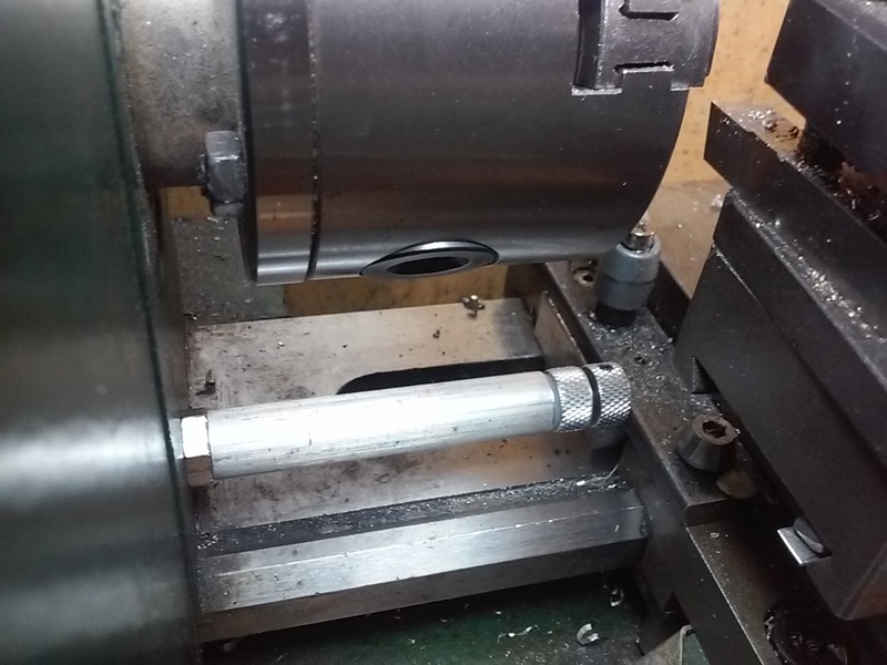
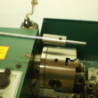 I use depth stops for repetitive cutoffs. While I now have a collection of depth stops, they are all based on this one. The basic idea is a sleeve locked in place with a set screw in the chuck and a rod locked in place with a setscrew in the sleeve. It is possible to use a single setscrew to lock both in place (easier depth adjustment), but it's only useful for short parts. A longer sleeve allows longer parts, but limits part diameter to ~5/8" minus sleeve thickness.
[ comment | link | top ]
 To bore concentric holes, the tailstock quill has to be parallel to the headstock spindle. The mini lathe tailstock only allows you you to make fore and aft adjustment for point to point alignment. I had read where you can use a MT3? dead center in the headstock and MT2 dead center in the tailstock to accomplish this. The problem is that it has nothing to do with parallelism.
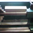
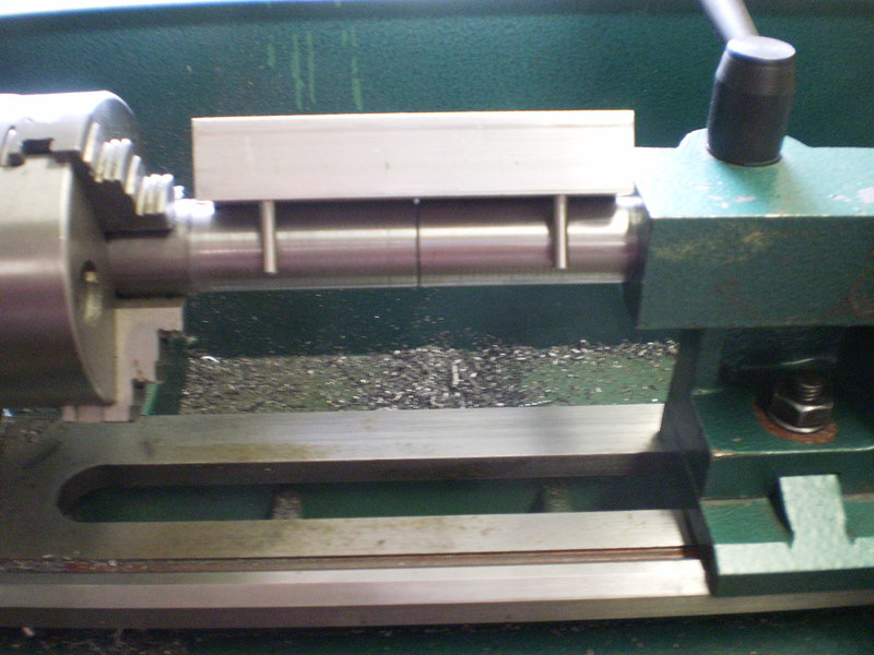
If you've ever held material and a square or straightedge up to a light to detect +/- .001" variations, the same principal applies to my method of tailstock alignment. I don't remember the dimensions, but I turned down a piece of cold rolled to the same diameter as the tailstock quill. My 3/4" square stock with two dowel pins provides a parallel contact edge. When a light is shown at the edge (from behind) any alignment issues are visible.
While I added a couple of setscrews and an adjusting screw for fore and aft adjustment, any other adjustments require material removal. My tailstock was both slightly counter-clockwise and slightly high on the headstock end. The castings are soft and the machining so irregular/rough that a bit of honing on the appropriate high spots had a noticeable effect.
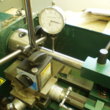 ...At the time it didn't occur to me to use a dial indicator on the carriage. I wouldn't say that either method is easier, or more accurate. The straightedge provides a better overall view of the alignment (or lack thereof) and the dial indicator provides by-the-numbers information, both are useful.
[ comment | link | top ]
Mini Lathe
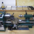
 My mini lathe is a Sieg SC2. I bought it at a Grizzly tent sale and had no clue that it was a brushless high-torque demo model (Grizzly is still selling the older C2). I've never used a C2, but I'm pretty sure I lucked out.
![]()
Carriage Stop
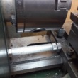
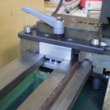
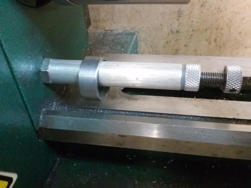
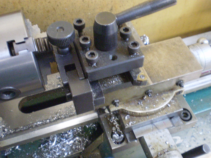
 A carriage stop is a must for any operation where relocating the cutter position using the compound slide is impractical. This stop uses an incremental thread (e.g. 1mm or 1/32" pitch) and a zero mark (e.g. the setscrew) so that the stop position can be accurately set, measured and reset at any time. For finer adjustment, a faceted head (e.g. a decagon for .01mm/~.0004") could be used. The stop has a range of ~2" with the minimum setting a bit less than I've ever needed, the maximum a lot more (...jinxed, I had to switch to a longer screw for this setup)
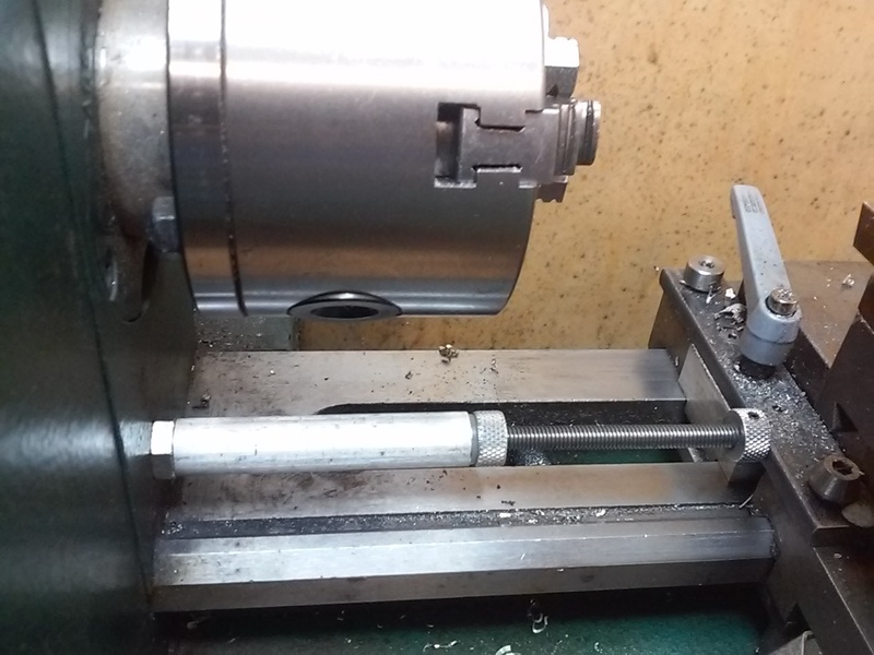
The body, knurled head and lock-nut were made from 1/2" aluminum rod. The knurled head was tapped, mounted to a threaded rod with a setscrew and then faced. The aluminum body was tapped for the threaded rod on one end and has a clearance hole on the other. Because tapping the clearance hole for a mounting stud would have required a larger diameter stud than I wanted, I used a short bolt for mounting. The aluminum is threaded for the bolt and the bolt was center drilled/tapped to mount it to the stud (a long setscrew). The mounting stud location is as low and to the front as I could get it - using my smallest cordless drill for drilling the pilot hole. Ideally the head of the stop would hit the carriage, but I had to be content with it hitting the top bar of my carriage lock.
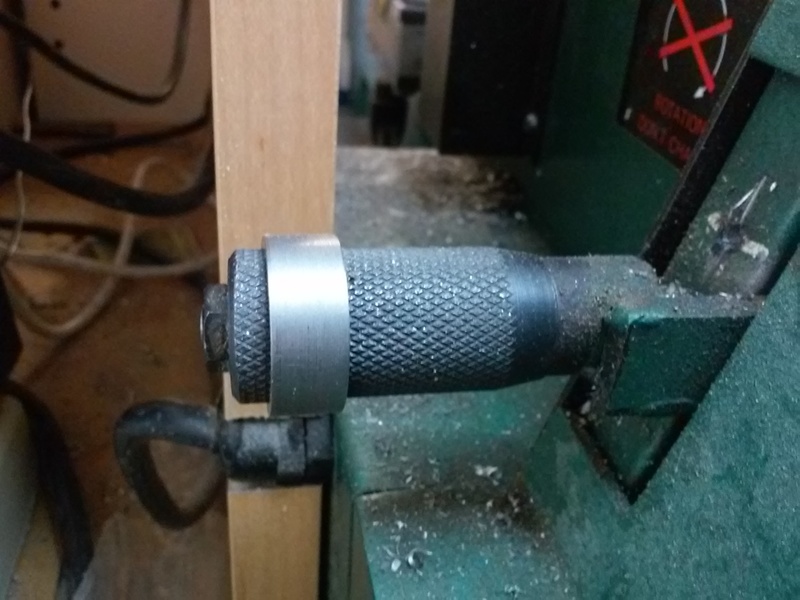
...Added a ring that goes on the drive lever to remind me to retract the stop.
...Made a limit switch attachment that hooks up to the chuck guard interlock wiring. 18sec YouTube video.
[ comment | link | top ]
Knurling
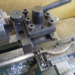
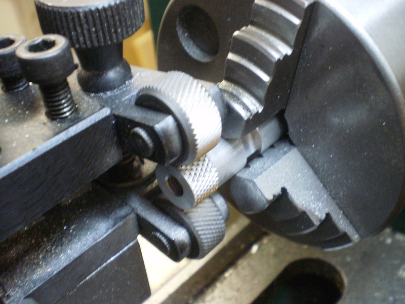
 I use a Grizzly T10056 scissors knurling tool with the small side lip butted to the back of the tool post. It's held in place with two of the three screws and located with almost no clearance between it, the tool post side and the chuck. I have a small centering reference arrow drawn on the carriage (near the bottom right of the image) that aligns the centers of the knurler wheels with the center of the chuck.
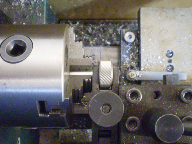
To setup, I start with the knurler centered, tighten the knurler until both wheels are touching the material to be knurled, back the cross slide off a few turns and then turn the knurler knob a bit more than a quarter turn. To knurl, I move the cross slide forward until both wheels are contacting the work hard enough to leave a decent impression. I then manually turn the chuck at least one full turn to insure I have a good pattern. That first turn is the most important and being a bit aggressive on the pressure helps to prevent a running/overlapping pattern. I then run the mill at slow speed and move the cross slide forward until the wheels are centered on the chuck (my arrow). I've been leaving it there for 30 seconds, about when I stop seeing flakes appearing on the knurling wheels. With larger diameters I have had to back the slide off a bit, (to be able to) turn the knob a bit tighter, and move the slide back forward to get nice pointy knurl peaks (on aluminum).
With the stock wheels I had to take a bit off of 1/2" stock to get a good knurl. I flattened those wheels trying to knurl something too hard. The replacement wheels (different brand) work fine on 1/2", but 5/8" needs to be turned down a bit. While the ideal material diameters for a given set of wheels should be easy to know, I didn't have much luck with the math (e.g. PJ's knurling pages). If I cannot get a good pattern on the first turn, I try a deeper first turn before resorting to turning the diameter down a bit. A deeper first turn is possible when only a portion of the wheels contacts the stock, e.g half on/off the left end of the material. At least with my wheels, knurling is much easier moving the carriage left to right.
[ comment | link | top ]
Quill Stop
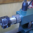
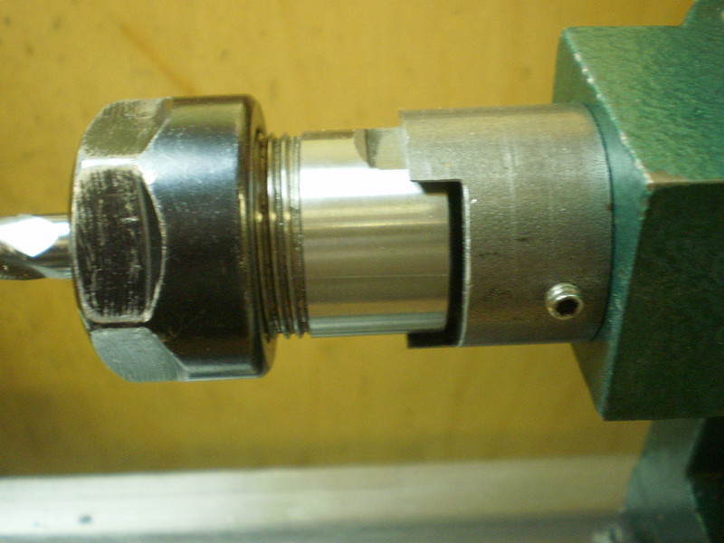
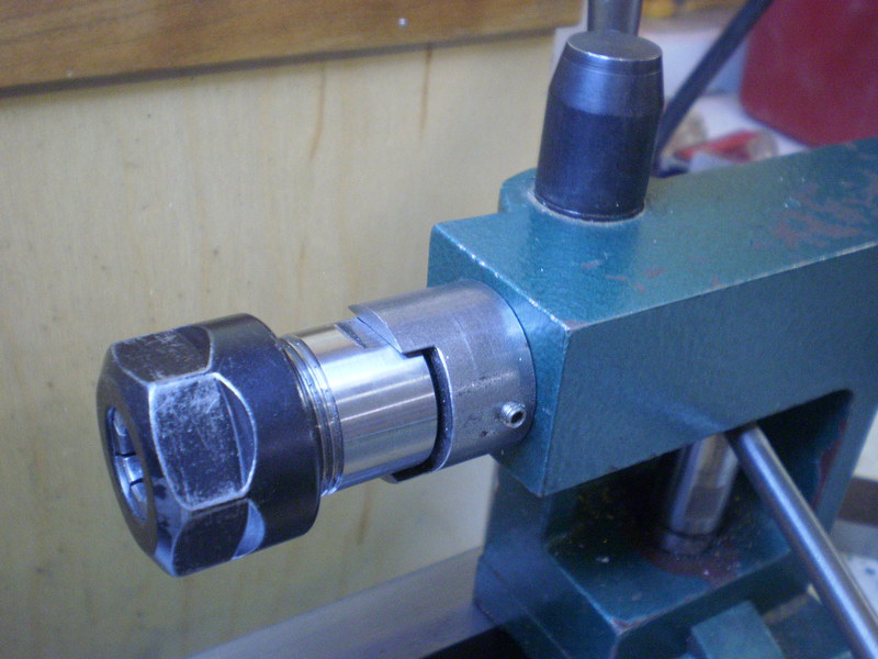 I've been using ER-20 collets for pretty much all of my milling, drilling, tapping and reaming. The quill stop solved two issues, bumping out whatever was held in the MT2 quill and needing a bit more tightening force when using ER collets. ER collets don't need to be tightened real hard, but they do need to be tightened a bit more than friction fit (sans drawbar) MT2 shank allows.
I used what I had, a piece of 1-1/8" cold rolled. I used a boring bar to get the ID to match the quill and drilled matching divots in the quill for the two (opposing) cone point set screws.
I had thought I might need something sturdier, but it has worked out real well. Standard length MT2 shanks still work and I can remove the ER chuck with a flat blade screwdriver stuck in the side slot. The automatic 0 setting when the quill is retracted is a big plus.
[ comment | link | top ]
Lead Screw Thrust Bearing
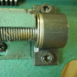
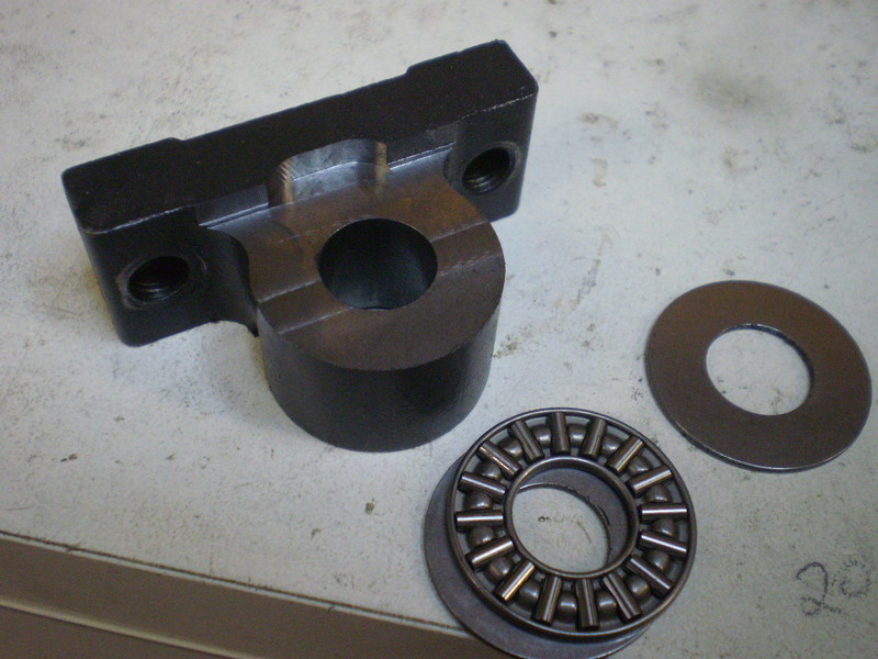
 I don't use the lead screw under power much, but but there was noticeable wear to the pillow block. I don't know if it's a common issue, I do keep the carriage pretty tight and the high torque motor does allow me to take pretty heavy cuts. Heavy facing using the lead screw as a carriage lock may have been a contributing factor. The last time I noticed wear, I flipped the mounting block around. With both sides worn and just happening to have the right size thrust bearings (AXK1226) on hand for another project, I decided to do something about it. It was a relatively simple mod with a bit of back and forth to remove just the right amount of material from the block.
[ comment | link | top ]
Carriage Lock
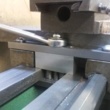
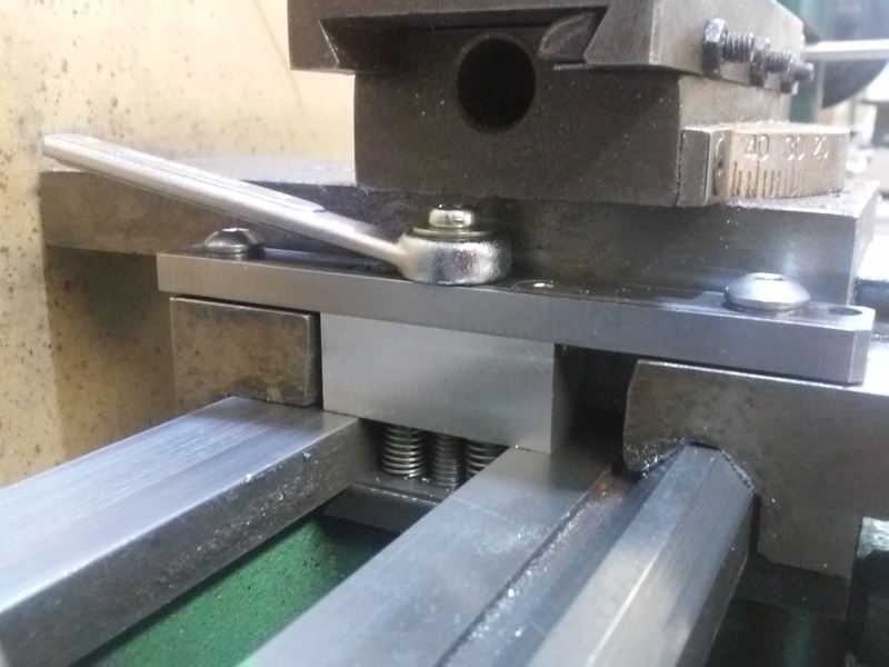
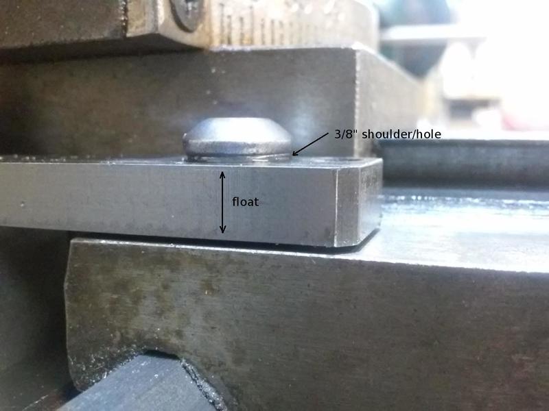
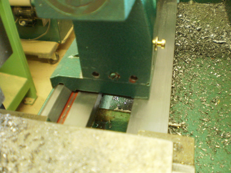
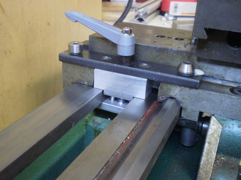 While engaging the threading lever limits carriage motion, relative to how tight it is adjusted, there will always be a bit of side play. Holding the carriage knob, in one or the other direction, while cranking the cross slide is not an ideal solution. I decided on a floating carriage lock that used the existing follower rest mounting holes (m6).
 The 1/4" steel mounting plate has reamed 8mm holes to accommodate m6 x 8 x 8mm shoulder bolts (= almost 1/16" of float), a chamfer on the bottom to clear the ragged carriage radius, a 5mm hole for the m5 lever knob and two countersunk 4mm holes for mounting a piece of 3/4 square stock to the bottom. The aluminum square stock was tapped and drilled to mount/match it to the top plate, and has two 3/16" pins press fit into the bottom. I then shaped the aluminum it to fit the space. Using 5/8" square stock (don't have any) would have been much easier. The bottom plate is 1/4" bar tapped for the lever knob and reamed for the two locating pins.
The spring between the aluminum pieces releases all clamping pressures with a 1/4 turn of the lever. The lever is not in the way for most operations, but is easy to remove. Removing the lever handle leaves a, still relatively easy to use, 8mm hex head.
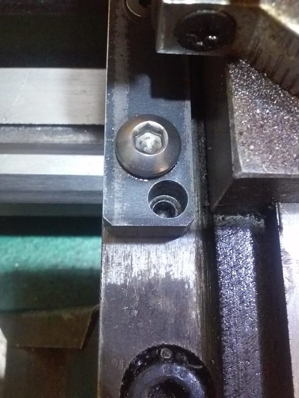
 ...A recent query prompted me to refine my year old design. In the process I came up with a low profile locking lever that is always out of the way - regardless of compound rest/slide angle/position. The clamping screw was beefed up to m6 and the head is tapped to allow holding a shortened 10mm box end wrench that can rotate 180 degrees. I ended up making my own shoulder bolts using tapped 3/8" drill rod for the shoulder. The main body is a bit long to accommodate a hole for through tapped top adjustable carriage gibes.
[ comment | link | top ]
Tailstock Lever Nut
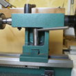
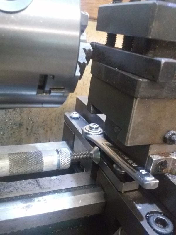
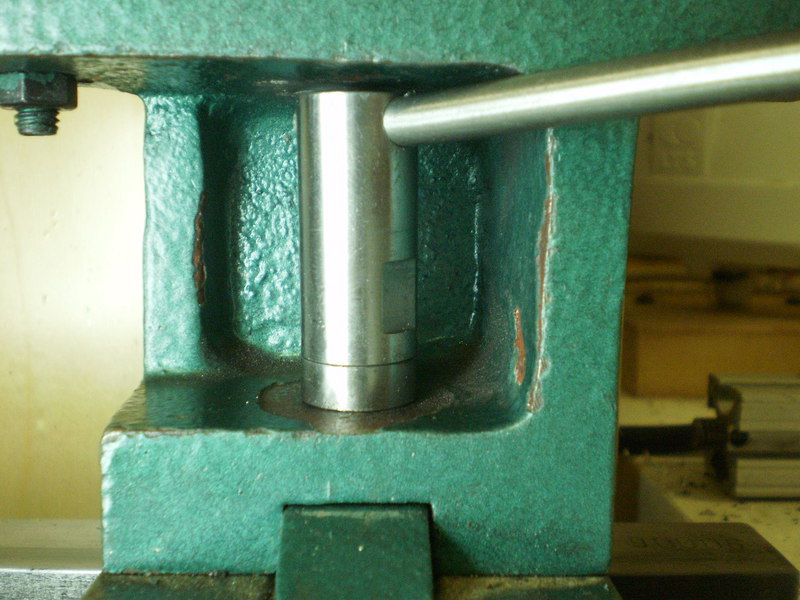
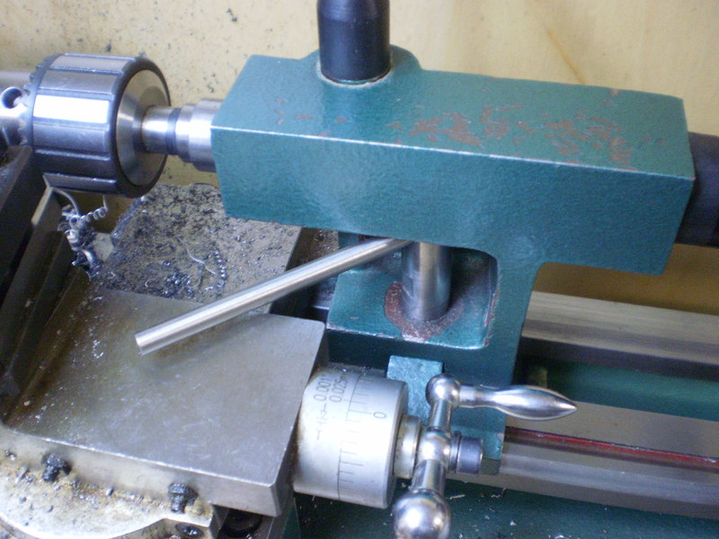
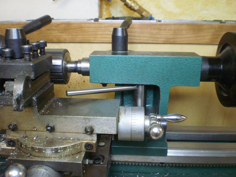
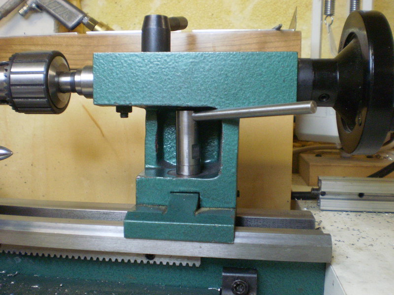 The popular cam lock tailstock mod was appealing, but I wanted a quicker solution. I do a lot of work with the tailstock close to the chuck and the main issue is that the nut is too low to easily get a wrench on it. My first thought was a taller nut (e.g. a stock m10 coupler nut), but I liked the idea of a lever. I realized that a lever would work if the nut was tall enough.
I used 5/8" drill rod for the cap nut and a thick washer, 1/4" for the lever. I had to trim the nut to get it to fit in the opening and then to get it so that the tailstock would slide freely when the lever was all the way to the right (adding a threaded sleeve on the stud tightened the sloppy action). I was left with plenty of room for tightening. It will take a lot of wear before the lever gets close to the quill guide pin/nut. I did put a slight bend in the lever for better vertical clearance. The flats on the nut were for a wrench and may have helped during the fitting process.
[ comment | link | top ]
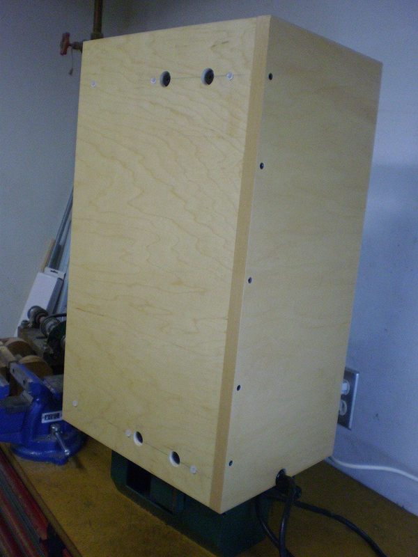
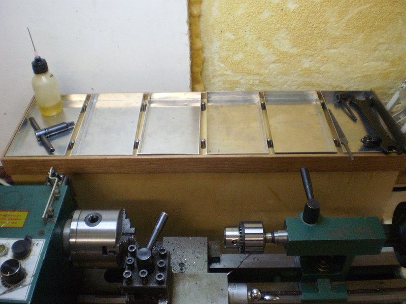
Backsplash Tray
There's only so much space on and around the lathe for tools and parts. Adding a tray to the top of the backsplash seemed like it would be a handy place for keeping tools and parts organized. Replacing the stock base tray and backsplash was the easiest way to accomplish that. I used some scrap prefinished Maple plywood and dowels/confirmats for assembly. The tray has a 1/2" lip made with Cherry edging and the bottom has six rubber bumpers to keep it from sliding around. The aluminum trays are working out well for both tools and parts. I also made a catch tray for easy cleaning and retrieval of fallen parts.
[ page | comments (2) - Friday, 08-May-2020 | top ]
Depth Stop
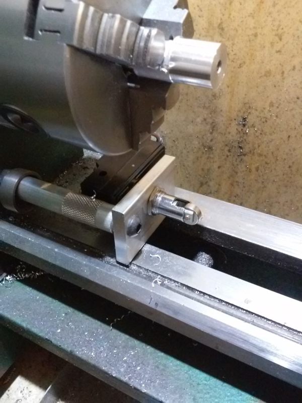
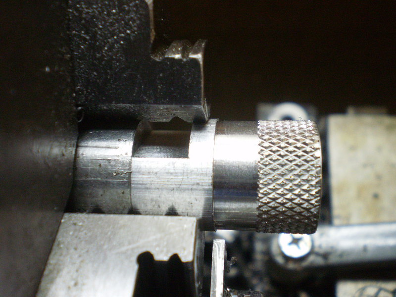
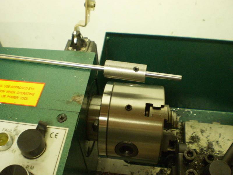 I use depth stops for repetitive cutoffs. While I now have a collection of depth stops, they are all based on this one. The basic idea is a sleeve locked in place with a set screw in the chuck and a rod locked in place with a setscrew in the sleeve. It is possible to use a single setscrew to lock both in place (easier depth adjustment), but it's only useful for short parts. A longer sleeve allows longer parts, but limits part diameter to ~5/8" minus sleeve thickness.
[ comment | link | top ]
Tailstock Alignment
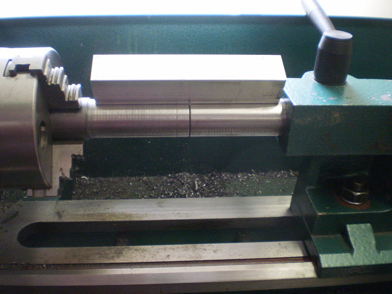 To bore concentric holes, the tailstock quill has to be parallel to the headstock spindle. The mini lathe tailstock only allows you you to make fore and aft adjustment for point to point alignment. I had read where you can use a MT3? dead center in the headstock and MT2 dead center in the tailstock to accomplish this. The problem is that it has nothing to do with parallelism.
If you've ever held material and a square or straightedge up to a light to detect +/- .001" variations, the same principal applies to my method of tailstock alignment. I don't remember the dimensions, but I turned down a piece of cold rolled to the same diameter as the tailstock quill. My 3/4" square stock with two dowel pins provides a parallel contact edge. When a light is shown at the edge (from behind) any alignment issues are visible.
While I added a couple of setscrews and an adjusting screw for fore and aft adjustment, any other adjustments require material removal. My tailstock was both slightly counter-clockwise and slightly high on the headstock end. The castings are soft and the machining so irregular/rough that a bit of honing on the appropriate high spots had a noticeable effect.
 ...At the time it didn't occur to me to use a dial indicator on the carriage. I wouldn't say that either method is easier, or more accurate. The straightedge provides a better overall view of the alignment (or lack thereof) and the dial indicator provides by-the-numbers information, both are useful.
[ comment | link | top ]